Autonomous Lunar Lander
UCSC Rocket Team
Project Description
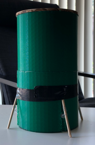
The Lunar Lander project is the Payload subteams’s design for the Payload Challenge of the NASA SLI competition 2020-2021. The payload is designed to fit inside the rocket pictured below.
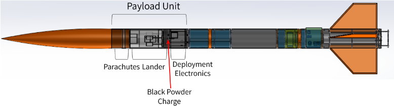
The Lander is the payload carried inside a 6” diameter model rocket that flies it to a 5000ft target apogee. The lander is designed to be deployed from the descending rocket when the launch vehicle is 500ft above ground level. Onboard deployment electronics sense the correct time to deploy or receive an override signal via radio to the ignite black powder charges. These charges exert a force to push the lander out of the vehicle. The lander then descends with the aid of a parachute and self-levels upon landing. Finally, it deploys a 360-degree camera and captures an image of its landing location, then sends the image back to the ground team.
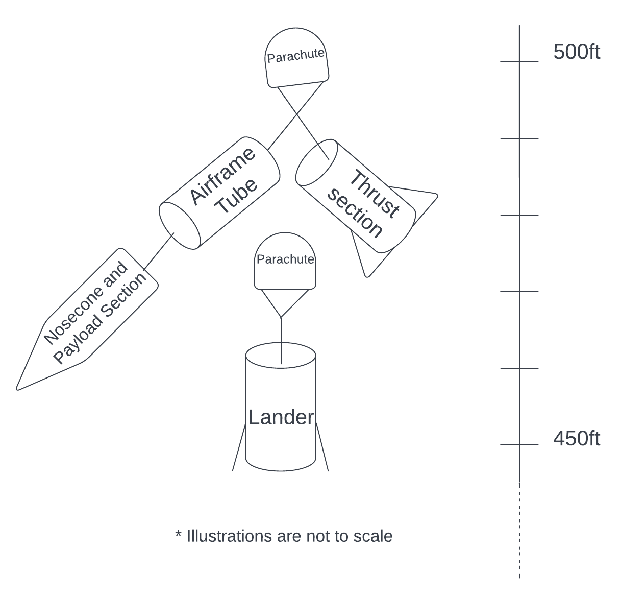
Below is a diagram detailing the payload's deployment:
The lander itself is built using the following diagrams:
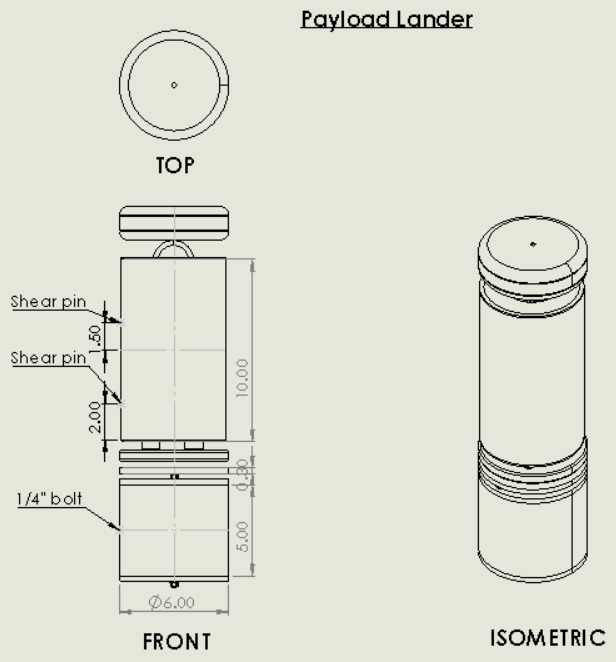
The lander is 10in tall and ~6in in diameter. In the rocket, it sits on top of the deployment electronics (newest deployment version discussed here). A mechanical drawing of the payload can be seen below:
Mission Success Criteria
Below is a timeline of a successful mission:
MSC#:
- All subsystems successfully initiated
- Deployment signal is successfully sent to the E-matches onboard at the correct altitude.
- The lander lands undamaged and the onboard IMU determines the lander is stationary.
- Lander’s initial angles are recorded.
- Autonomous leveling system operates motors to level the lander.
- Lander’s final angles are recorded.
- Lander raises the 360-degree camera and triggers it to capture an image of the landing site.
- Image is sent to the ground team.
- Image is received by ground team.
Lander Design - Electronics
Components
- Raspberry Pi Zero W
- Adafruit BNO055 Absolute Orientation Sensor
- 5x DC Motors
- 3x L298n Dual Motor Drivers
- 4G Network Module
- 360-Degree Camera
- 2x LiPo Batteries
The Lander uses off-the-shelf sensors and electronic components to achieve its task of autonomously self-leveling and transmitting 360-degree images. The main computer on board is a Raspberry Pi Zero W which was chosen for its compact form factor and network capabilities. The second most essential component is the Adafruit BNO055 absolute orientation sensor which provides accurate Euler angle measurements. These components help in creating the signals sent to the L298N motor drivers that drive the 4 DC motors to level the lander.
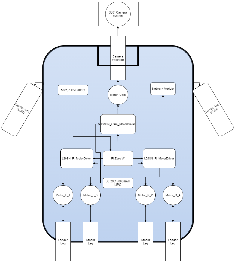
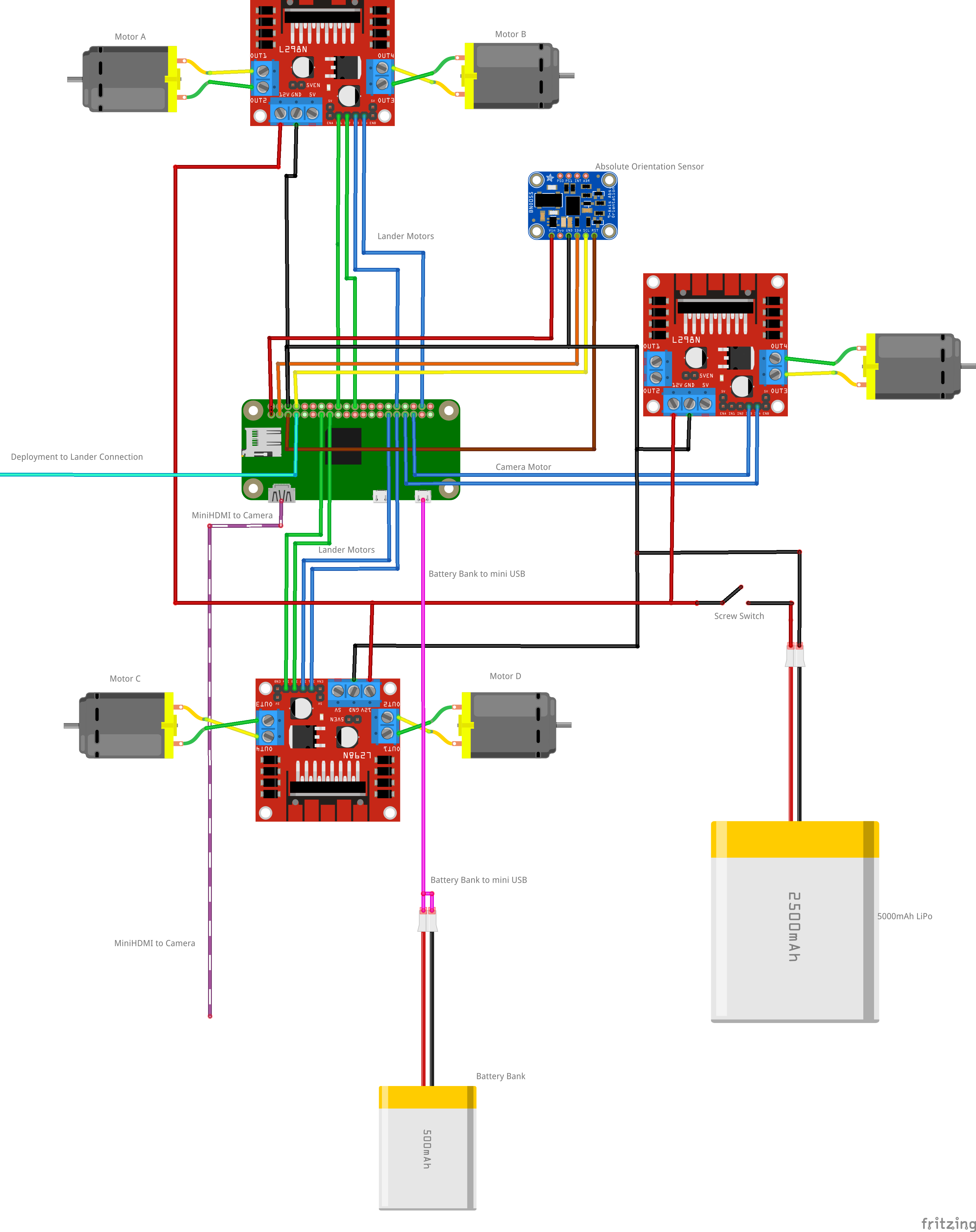
Lander Circuit
The image below shows how the lander components are wired.
Lander Design - Software
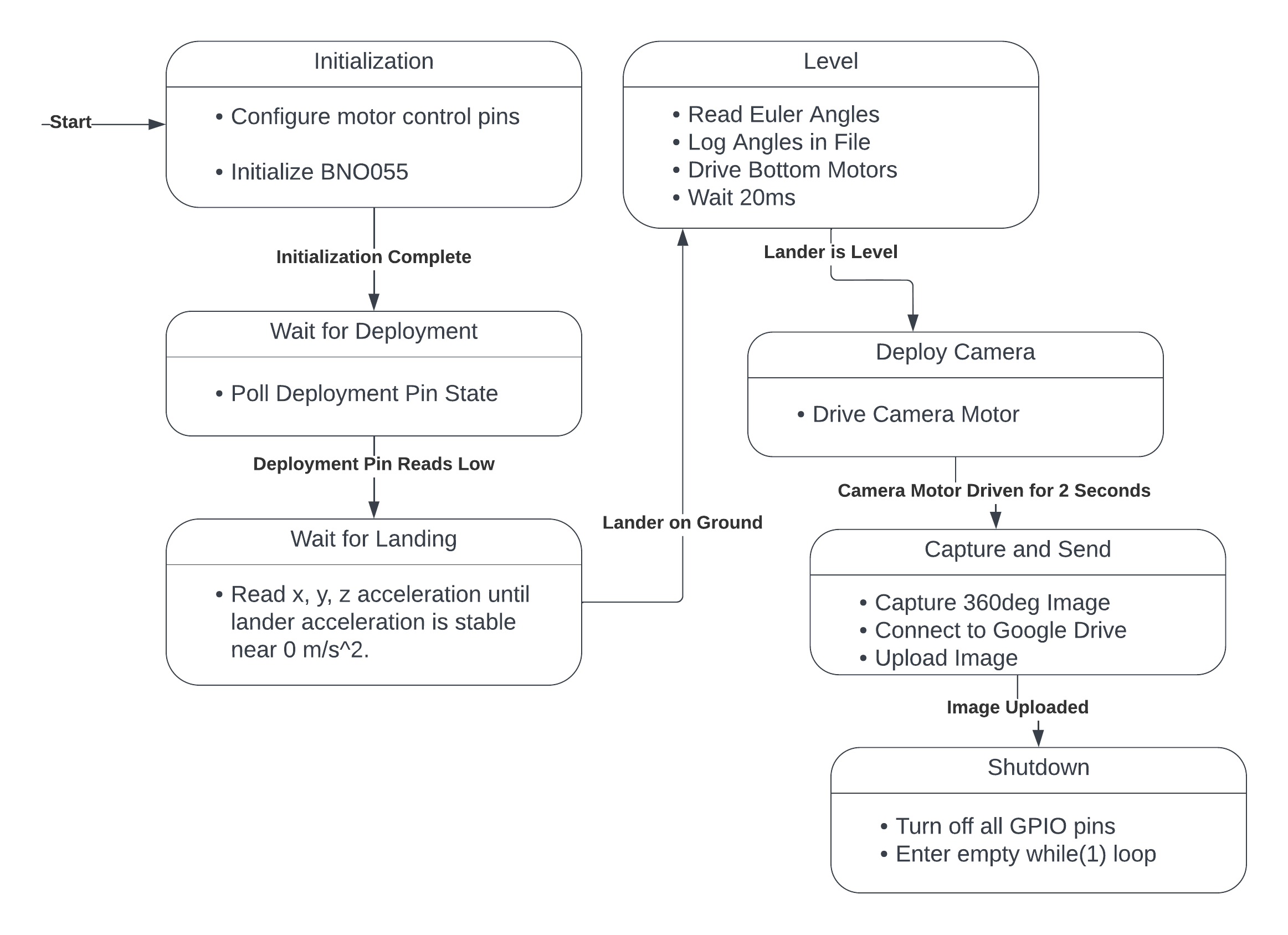
This state machine was implemented in python on the RPi Zero W. The code polls the IMU to determine its acceleration state then uses the orientation data to level the lander.
The lander is leveled by sending PWM and direction commands to the motor drivers which spin the motors as necessary to move the linear actuators.
Lastly, the camera is deployed by actuating a motor controlling the camera deployment mechanism. The camera then captures and sends the image to the ground team.
Deployment Design - Electronics
Components
- Adafruit Feather 32u4 RFM95
- Adafruit BMP 388 Barometric Altimeter
- 2x DRV8838 Motor Drivers
- 9V Batteries
The deployment circuit uses an Adafruit microcontroller with an onboard radio module, a barometric altimeter and two motor drivers to supply the current necessary to ignite the black powder charge’s E-match.
Read about how I improved this design and made it autonomous here.
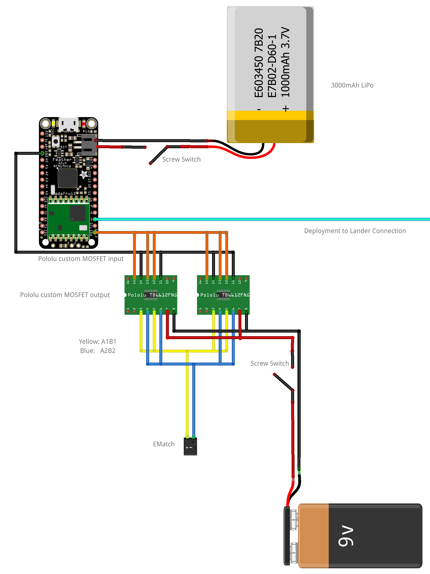
Deployment Circuit
TBelow is a wiring diagram for the circuit:
Deployment Design - Software
The deployment, implemented in C++ using the Arduino framework, follows the diagram below.
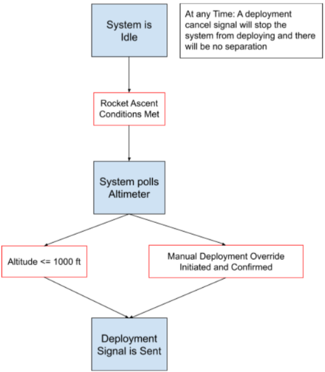
The BMP388 sensor is set up to provide data via I2C and determines when the deployment signal is to be ignited.
The Motor Drivers are set up to take a PWM signal with a varying duty cycle to provide the ematch with the necessary current to ignite the charges.
The onboard radio module talks to the microcontroller via SPI and tells it when the override commands are sent.
Results
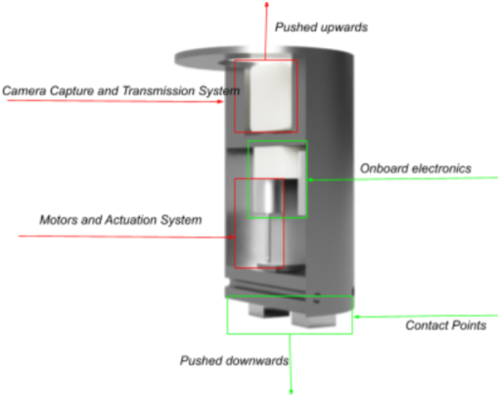
Below are images of the finalized lander:
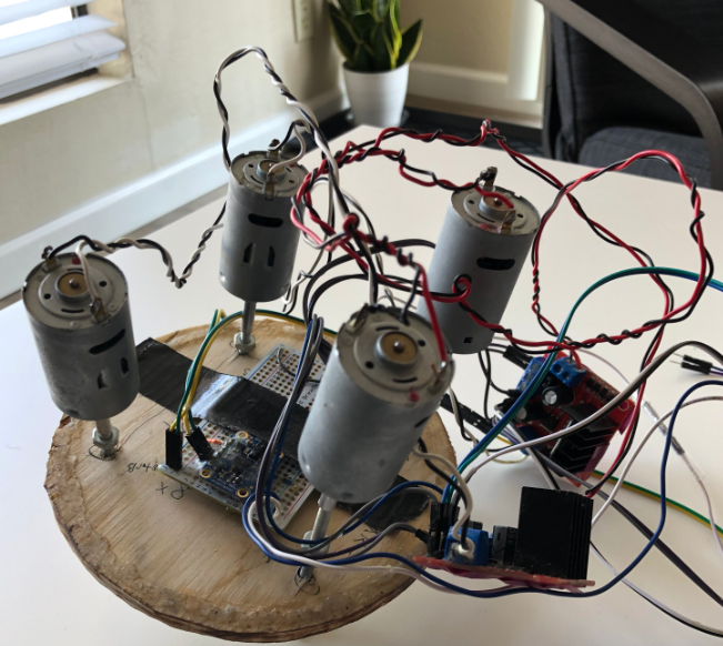
Unfortunately, due to COVID-19 restrictions, the team was not able to fly the rocket or test the lander. The lander was fully assembled and was able to successfully self-level within the 5-degree tolerance, but this was not tested outside the lab environment. Sadly, I can’t track down the one video I had of it working :(