Autonomous Payload Deployment Mechanism
UCSC Rocket Team
Project Description
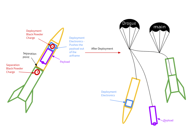
The aim of this project is to build an embedded system that can sense certain rocket launch condition and autonomously deploy the vehicle’s payload. The system is required to sense the altitude of the rocket and when it reaches its apogee, then drive a high current E-match to ignite black powder charges. The system is also required to have at least 2 hour standby time. After many iterations, the system described below was built using an Arduino Nano and multiple sensors and electronics.
The system works by polling its altitude sensors as well as a digital separation signal to determine when the vehicle’s separation event has occurred, then drives an NPN transistor to ignite the E-matches that detonate the black powder charges used to push the payload out of the rocket. The separation signal is a simple wire placed at the rocket’s separation point and acts as a switch. Breaking the wire indicates that the airframe sections have separated.
Testing Results
In Vehicle Ground Testing
The video shows the results of testing the rocket’s separating point after detonating a black powder charge.
System on a Breadboard Testing
This video shows results of testing the system while it was in the breadboarding stage. This was the final iteration of the design before moving to the next stage. The new addition to the circuit is a wire from ground to a Nano input pin, signaling when the airframe has been separated. The switch is used as an altimeter bypass to avoid having to change the breadboard’s altitude.
Deployment Circuit
Components list:
- Arduino Nano
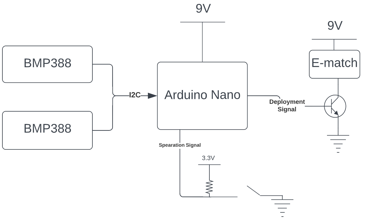
- 2x BMP388 barometric altimeters
- 1x NPN transistor(PN2222)
- 2x 9V batteries
- Assorted resistors and LEDs
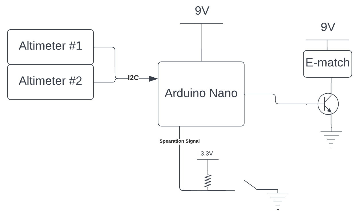
The circuit uses two BMP388 sensors for redundancy and noise reduction. These sensors provide altitude data crucial to the deployment algorithm. There are also multiple switches wired indicating when the airframe has separated. These signals are processed by a 5V logic Arduino Nano which is powered by a 9V battery. Once it determines apogee conditions are met, it outputs a 5V high signal to the NPN transistor’s base pin. This closes the circuit and flows current from a separate 9V battery directly into the E-matches.
Deployment Software
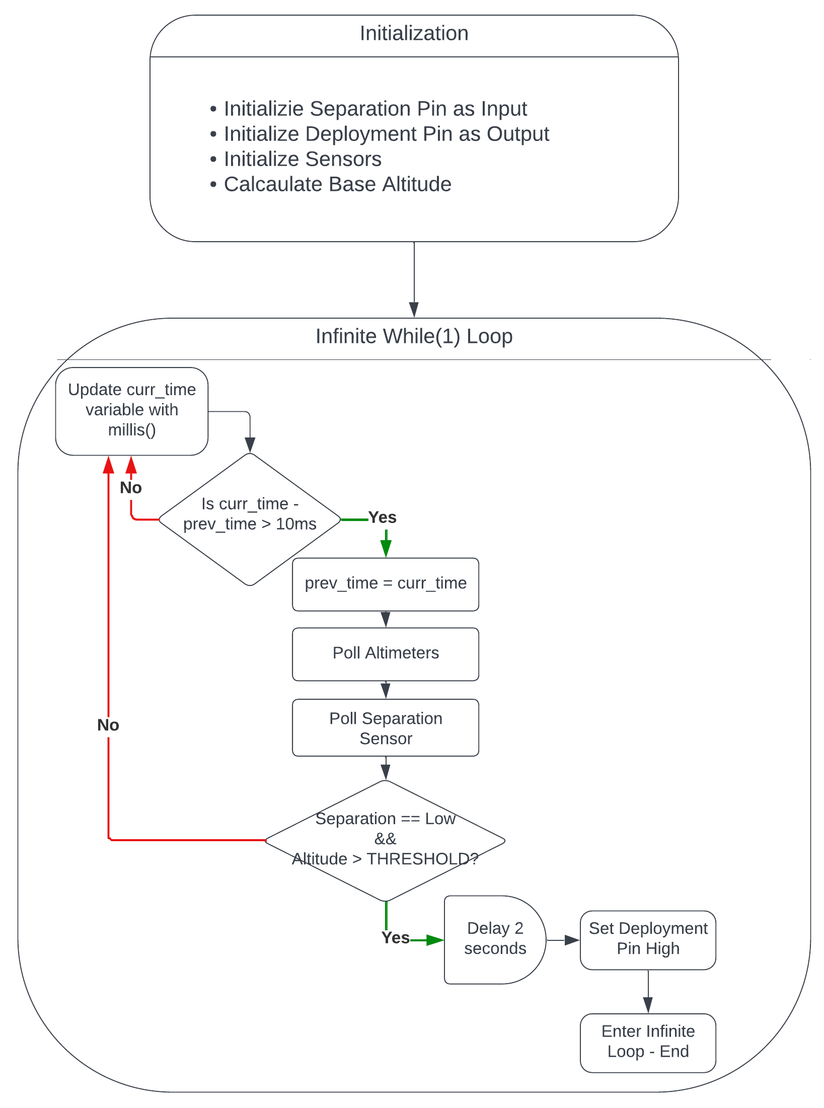
The Arduino program first initializes the necessary pins and sensors in the setup function, then enters the infinite loop. In the loop, it polls the altitude sensors and all setup separation pins. Once the altitude reaches a set altitude threshold close to the calculated theoretical vehicle apogee and the separation event is detected after the switch states change, the deployment conditions are met. The Nano then waits for 2 seconds allowing the parachutes to deploy untangled, then sends a high signal to the deployment circuit to detonate the black powder.
Mechanical Features
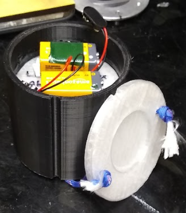
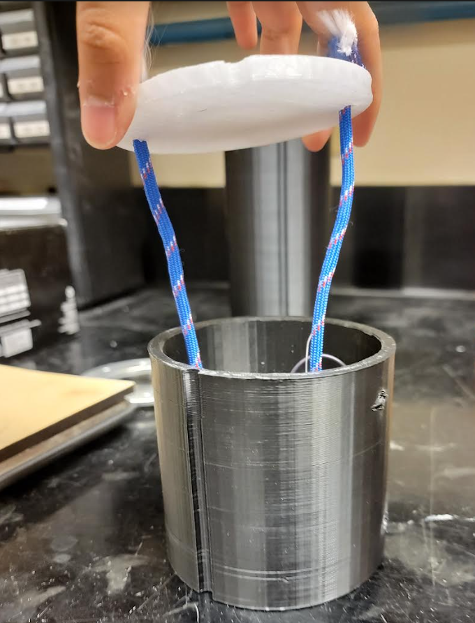
The deployment electronics are designed to sit on one side small, 3.5in diameter plate. The 9V batteries sit on the back side of thee plate. The black powder charges are mounted on a second plate of the same size and it sits on top of the electronics. This plate is the main barrier protecting the deployment electronics from the pressure charge. Lastly, there is a third disk (pictured below) which sits on top of the black powder charges. This disk is loosely tethered to the airframe and is used take the impact force of black powder detonation to push the payload out of the airframe. This ensures that the payload is not harmed during deployment.
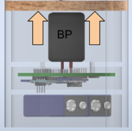
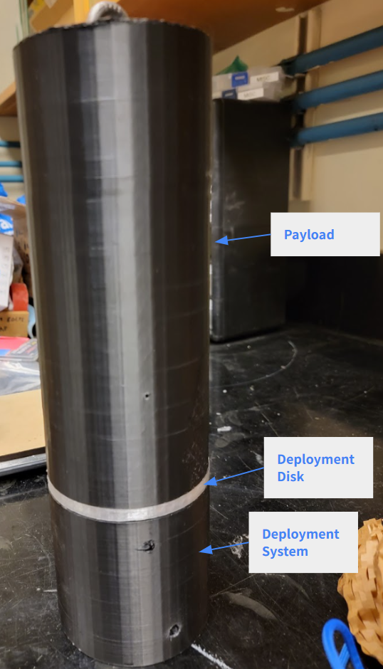
Finally, this is how the components sit together:
Necessary Improvements
For this system to be more robust when autonomous and less prone to mistimed signals, it could use more information about the vehicle’s attitude. In nearly all cases, the rocket begins to tilt as it reaches its apogee which is information that can be captured by well calibrated IMU. The rocket being horizontal instead of vertical is another event indicating apogee.
Another thing is to use the altitude’s rate of change instead of direct altitude measurements to determine when the vehicle is nearing apogee. Currently the system uses a defined theoretical altitude value to determine apogee which is specific to one vehicle. If the system instead uses the rate of change in the altitude data, it can tell when the system is coming to its maximum climb. This would generalize the system and make it easier to integrate in any launch vehicle as well as ensure that deployment is successful even if the vehicle misses its calculated apogee.