Mechatronics Autonomous Robot
UCSC - Mechatronics
Project Description
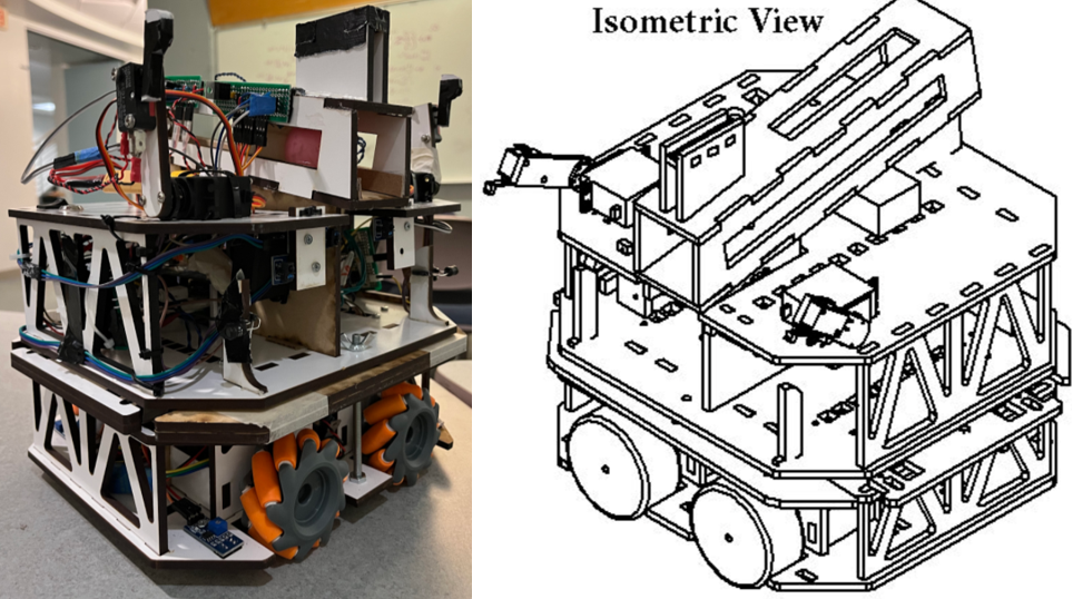
This robot, or "Rob", was the result of a 5 weeklong final project for ECE 118 - Intro to Mechatronics. The project merges software, electrical, mechanical, and systems engineering as well as project management to produce a fully functioning autonomous rover capable of traversing randomly generated fields and solving difficult tasks for each field.
Here is a video of the robot completing a randomly generated field for the final checkoff:
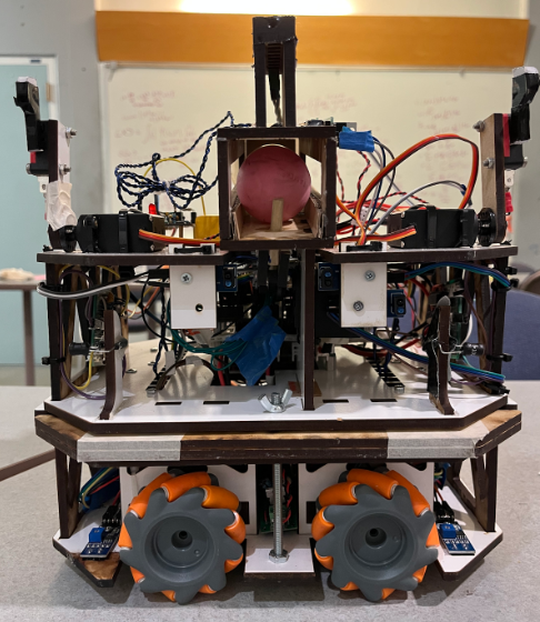
Rob the robot was developed in C on a PIC32 microcontroller. The logic for the robot was built on an event-driven multi-level hierarchical state machine that uses over 15 sensors and drives 4 mecanum wheels. Multiple custom-built signal detection sensors were used to tell when Rob has detected the presence of a vat tower or has found the correct side and hole to deposit the ball. The robot was designed in SOLIDWORKS 2018, and laser cut out of 0.2in thick MDF boards. It was a large assembly with multiple parts, so the equations function in SOLIDWORKS was used to quickly change mechanical parameters when necessary. In the end, Rob was one of the few robots able to clear fields efficiently in under one minute.
The Challenge
The challenge is to build a small autonomous robot that can navigate a standard field and advance through the field while avoiding the pit in the center. The robot must locate 2 out of 3 randomly placed vat towers, recognize the single correct side, then find the correct hole in which to deposit a ping-pong ball. All while avoiding a randomly placed obstacle on the field.The robots begin in a random orientation in one of the four corners of the map and are expected to solve 2 out of 3 towers in under 2 minutes and remain in bounds.
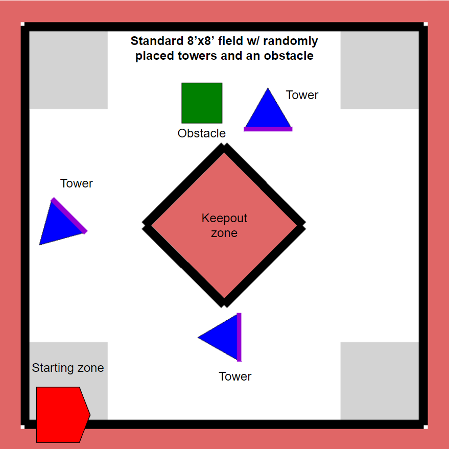
The field is white and 8’x8’ ft large with boundaries marked by 2” black tape. The keep out zone is similarly marked by 2" black tape.
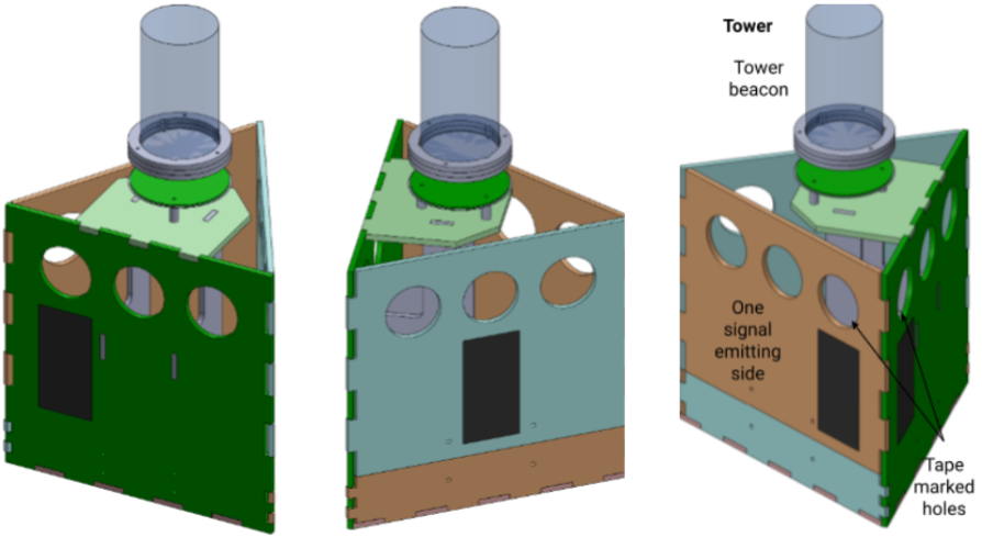
The towers have beacons at the top which emit a strong 2kHz IR signal. A 24-26kHz track wire sits behind one of the three sides of each tower and one hole is marked by tape on each of the three sides.
Requirements
To pass the final checkoff, the robot must solve two randomly placed towers by:
- Locating the signal emitting towers
- Finding the correct side of a tower
- Depositing a ping pong ball in the tape marked hole on the correct side
- Avoiding the box obstacle
The Team
The team worked tirelessly over 12 hours a day for nearly five weeks to produce a smart rover with an efficient field completion time.
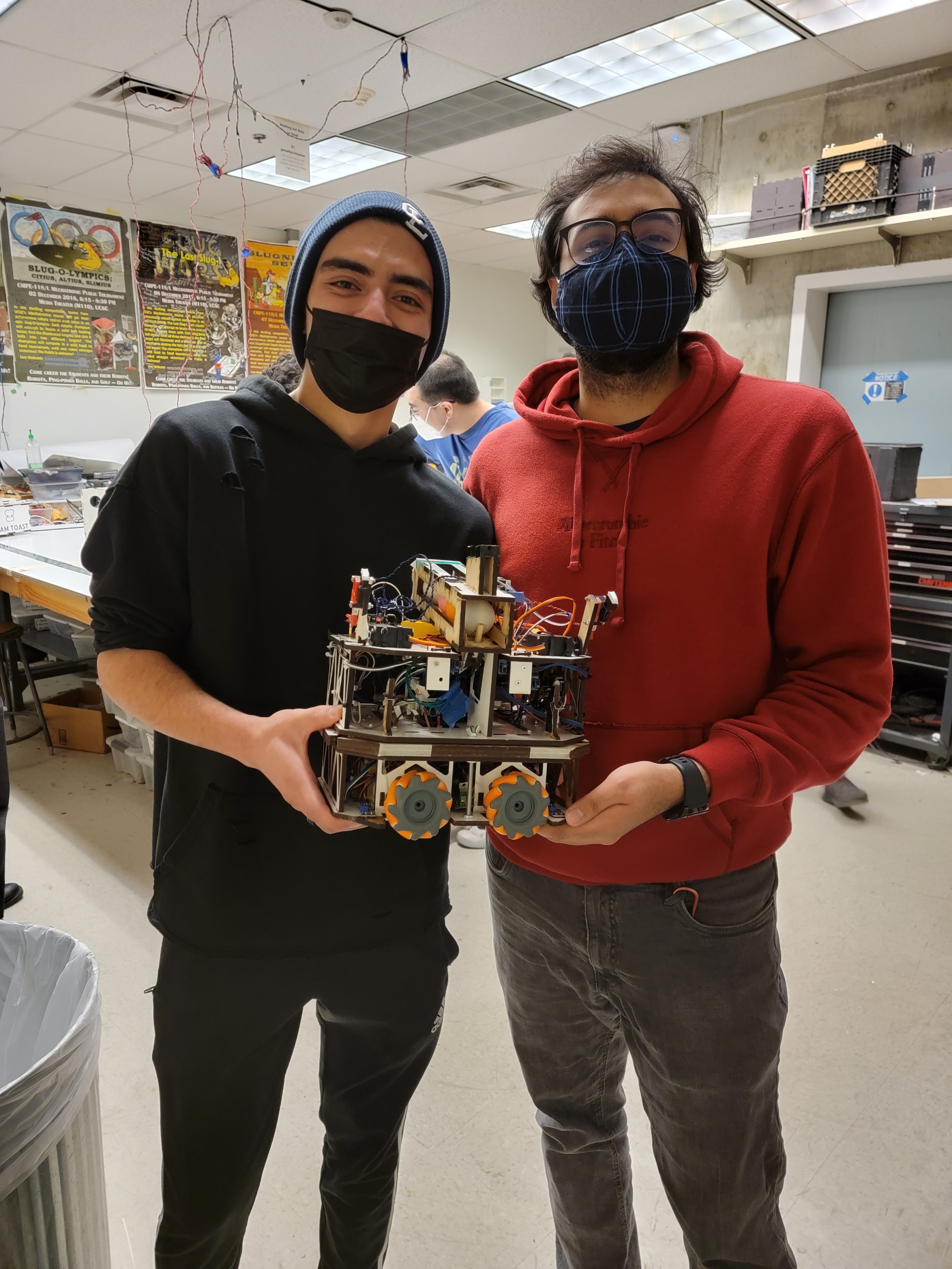
In this project, I took charge of software development and system engineering. I also aided with electrical engineering and testing the bot’s many circuits.
Robot Implementation
System Architecture
The system diagram below shows all the components that went into creating Rob. A PIC32 microcontroller was the main computer on board. A total of 16 different sensors and 7 motors were connected to it.
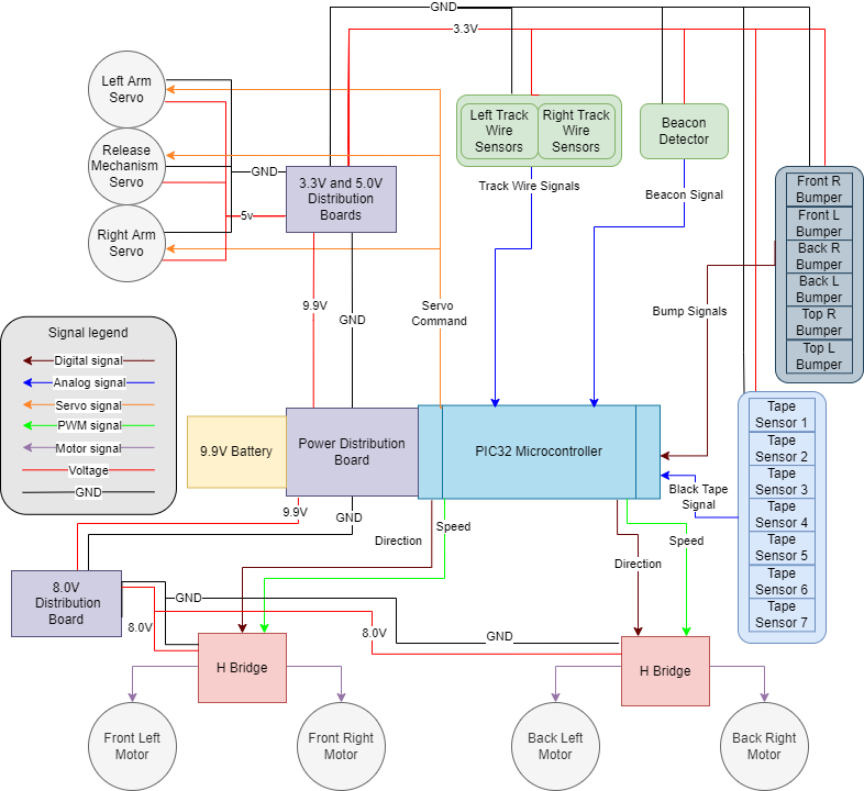
The microcontroller was powered by a power distribution board which is connected to a 9.9V LiFe battery and provides the PIC32 with a clean power signal and has multiple 9.9V output ports. Custom power distribution boards were built using voltage regulators to supply 3.3V and 5.0V outputs where necessary.
The robot utilizes:
- 1 custom built 2kHz beacon detector that provides analog input and senses signals from up to 10’ far.
- 2 custom built Track Wire (24-26kHz) detection circuits. The difference of these analog signals efficiently determines where the correct side is.
- 3 Servo motors to move the alignment arms and move the release mechanism.
- 4 DC motors to drive four mecanum wheels.
- 6 roller switches as bump sensors to tell when Rob has bumped into an obstacle.
- 7 tape sensors that run on 3.3V to tell when it is crossing the map’s boundaries and when it has found the tape marked holes.
All sensors ran on 3.3V as the PIC32 uses 3.3V logic levels. The servo motors were powered with a 5.0V signal and the DC motors were powered by a nominal 8.0V signal to prevent battery voltage variations from affecting the speed of the robot.
Hysteresis bounds were imposed on all analog sensors to reject noise and prevent the spamming of events. Digital signals such as the bump sensors were debounced using a 200Hz timer to clean up the signal.
Events and Services Framework
The software runs on a custom task scheduling framework that polls for continuously polls for events and services any that sensed/generated. It follows this diagram:
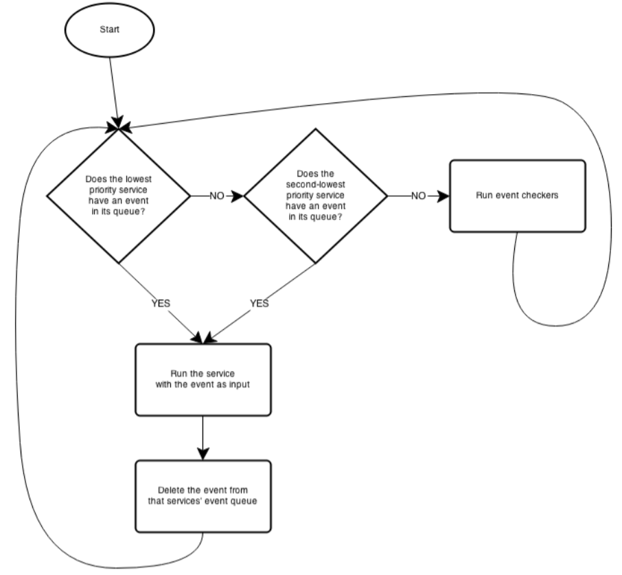
Events are detectable changes in the system. Services are functions designed to react to any generated event. This is what makes the robot event-driven. The robot has multiple event checkers for each sensor and peripheral and only acts when there is detectable change that has caused an event.
Hierarchical State Machine
This project was developed in C on a PIC32 microcontroller provided as class material. The code is in a private repository to keep academic integrity.
The hierarchical state machine (HSM) described below was developed on the Events and Services Framework. The framework continuously polls for detectable changes in the system and posts them as events to specific service functions that handle them.
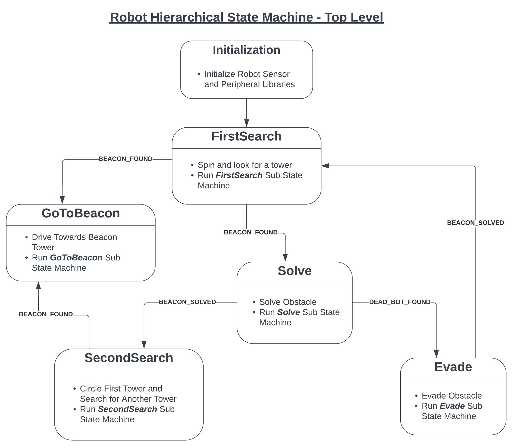
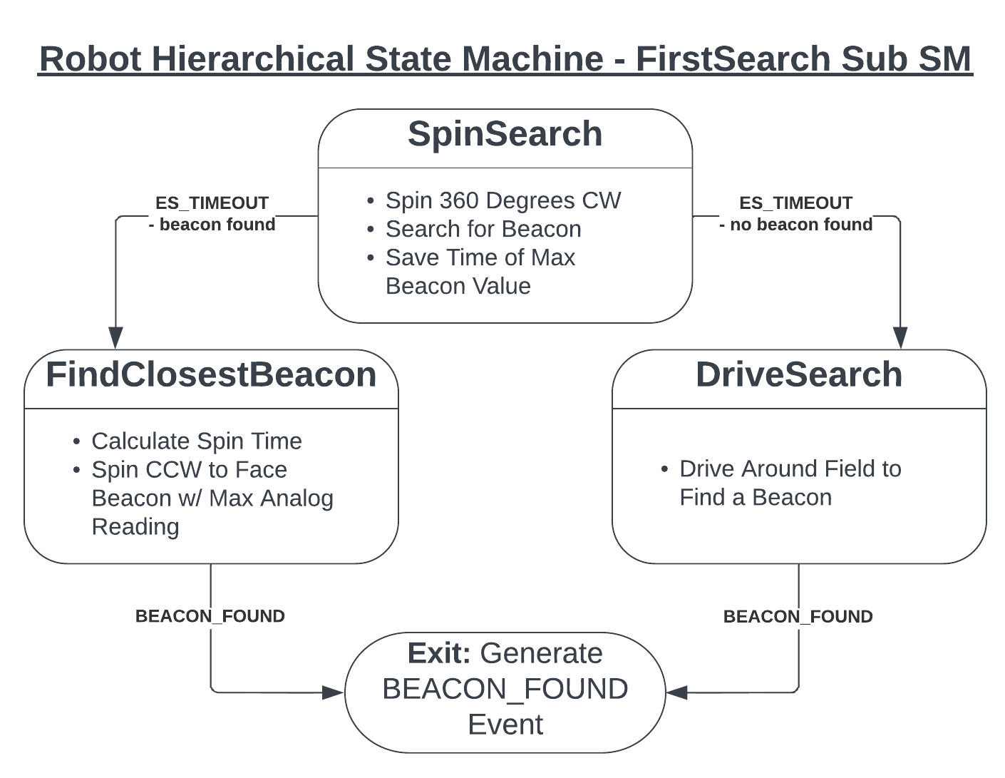
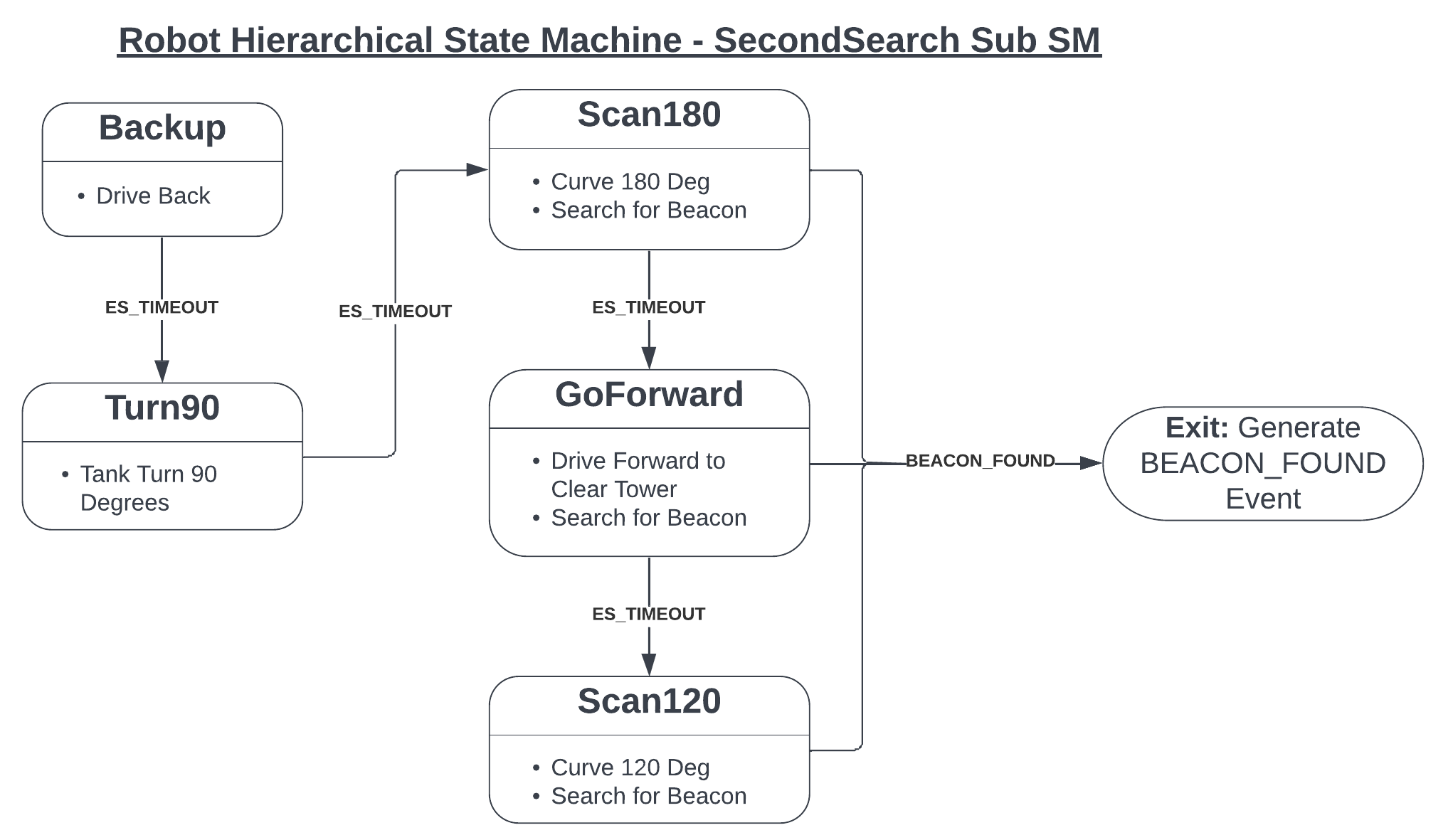
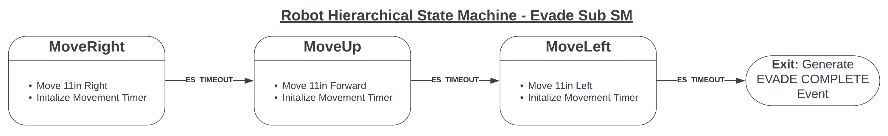
This level of the state machine defines the actions Rob takes at a high level. Rob starts in the FirstSearch state where it tries to find the first beacon, then goes enters the GoToBeacon state when it finds the closest one. After this Rob enters the Solve state. Here Rob either solves the tower or determines it has found the dead robot obstacle on the field. If Rob solves the tower, it performs the SecondSearch maneuver until it finds the second tower’s beacon and repeats the approach and solving process. If Rob determines that it has bumped into an obstacle that is not a vat tower, it enters the Evade state then returns to the first search state.
Each bubble in the top level of the HSM above defines a lower-level state machine that handles the larger task at hand.
More details on the Solve sub state machine coming soon!
Electronics
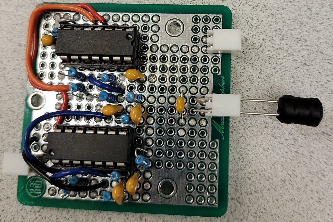
The robot uses two different custom-built sensors. See the Signal Detectors page for a more in depth description.
The robot uses a 2kHz Beacon Detector soldered to a perfboard as shown below:
As well as a 25kHz track wire detector, also soldered onto a perfboard and shown below:
Read more about these circuits and find their schematics here.
Unique Features
While most teams opted for a simple two-wheel design, Rob uses four mecanum drive wheels allowing it to use unique maneuvers to traverse the field. This simple modification meant that the software to drive Rob is slightly more complex but made solving the towers much easier and faster.
Rob also has two moving arms and two tank wire detectors instead of one. Rob uses the moving arms to quickly align with the face of a tower then can immediately tell where the correct side is based on the difference of the signals from the two track wire detectors.
Rob has a two-step launch process in which the launch key and the main switch must be used to ARM the robot. The two switches connected in series.