Autonomous Water Sampling Airship
Vehicle Flight Software and Sampling Payload System Design
Project Description
The importance of water for our planet and our species cannot be understated, and hydrologists have the essential task of maintaining and testing the water deposits around the world. For this, they require accurate measurement of multiple parameters at multiple locations of any given water body. This is usually done with a multiparameter sensor stack known as a sonde. With many of these water bodies in remote and hard-to-reach locations, sending a hydrologist out to conduct water quality assessments can be difficult and time-consuming. A solution is to construct an Unmanned Autonomous Vehicle (UAV) with the sonde onboard, which would travel to these locations by air. However, current UAV technologies lack the ability to hover for lengthy periods of time while also maintaining a long vehicle range, characteristics necessary for this application of hydrology research in remote areas.
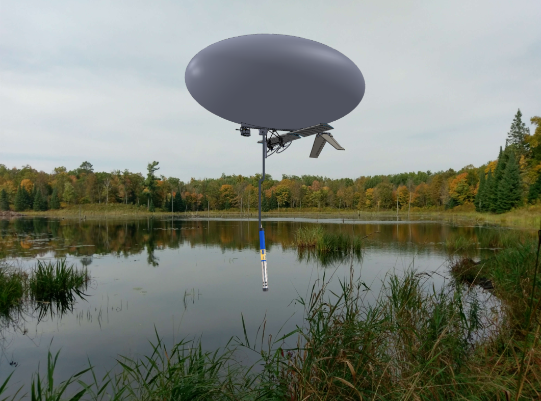
The aim of this project is to design and build an autonomous lighter-than-air UAV and payload delivery mechanism that can fly to remote bodies of water, efficiently hover over sampling locations, and deploy an industry-standard sensor array used by hydrologists to gather data about the water’s health and assess its quality. This would eliminate the need for hydrologists to travel, allowing for more efficient data collection.
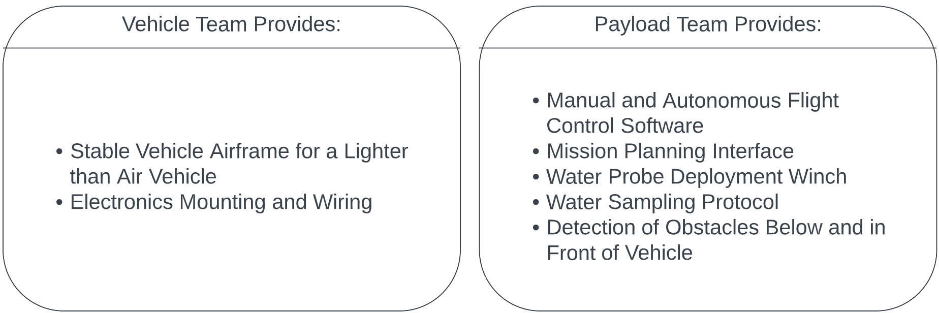
To achieve this goal, the project responsibilities were divided between two cross-functional teams. The Vehicle Team is responsible for delivering and maintaining the vehicle airframe. The Payload Team is then responsible for designing the embedded systems to fly the vehicle and avoid obstacles, the sensor delivery mechanism, and the sampling protocol.
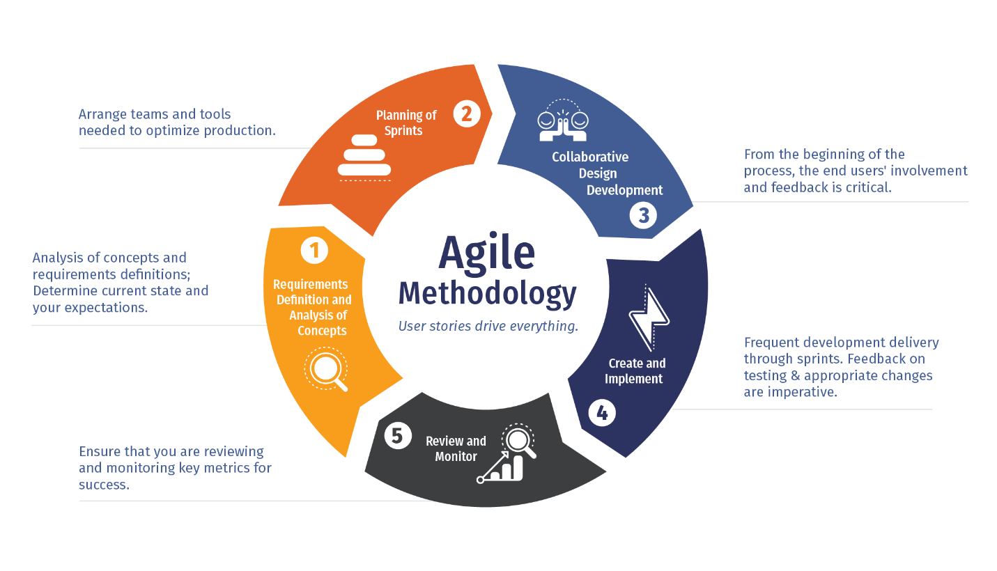
The team used Agile methodologies and requirements-driven design to define system requirements, plan sprint goals and tasks, as well as develop, implement, and test project components. This helped the team focus on the end user’s perspective as well as hit project milestones and provide quantifiable deliverables in an efficient and timely manner.
System Overview of the Airship Project
The diagram below is a system level breakdown of the project’s essential components.
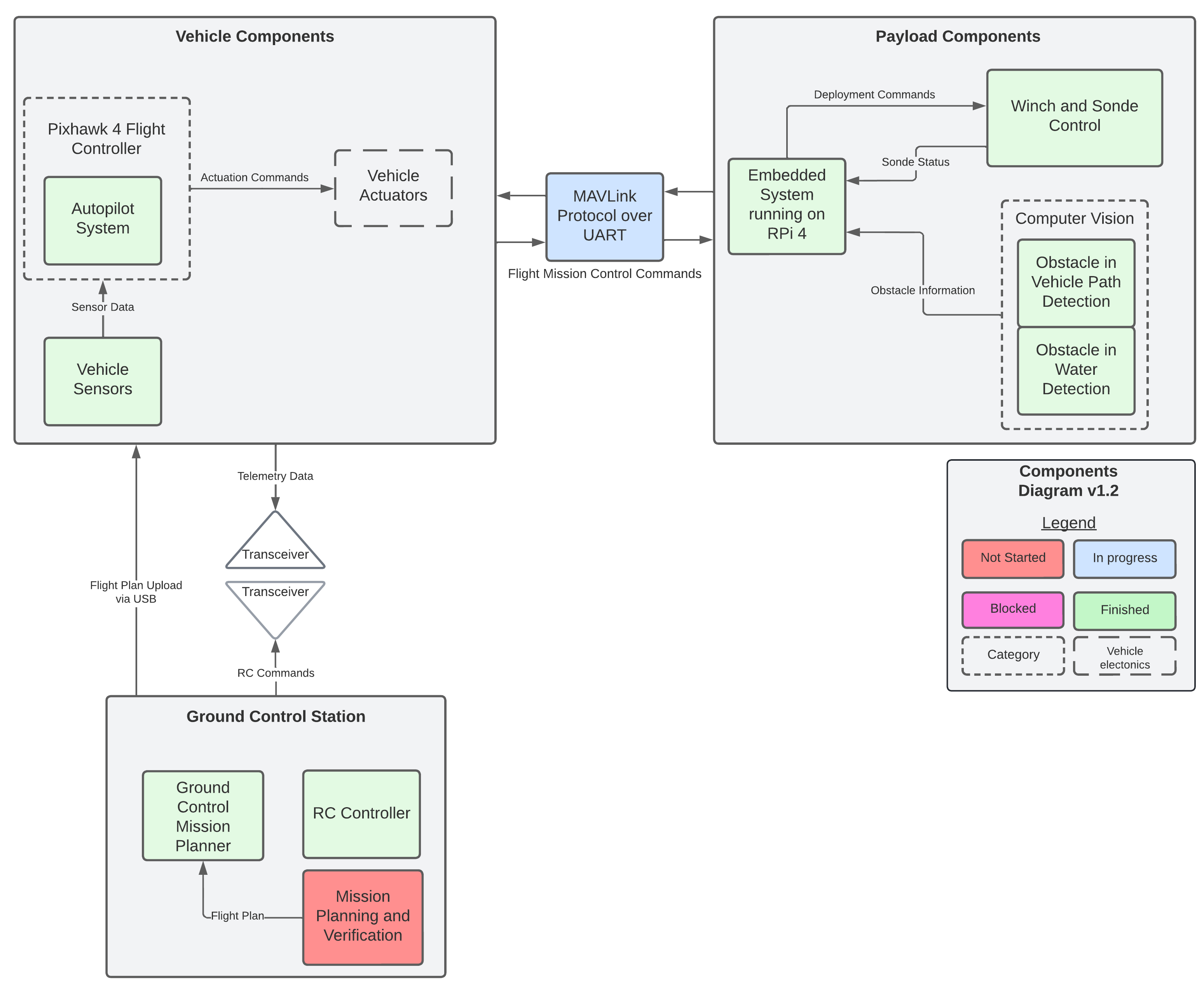
The primary subsystems in this project include autopilot software running on the Pixhawk 4 flight controller, obstacle and water detection through computer vision algorithms, embedded software to control the sonde delivery winch mechanism running on a separate On Board Computer (OBC), as well as RF and MAVLink communication layers to connect between the two OBC boards.
My responsibility as the Vehicle Flight Software Engineer is to use open-source autopilot software (ArduPilot) to control the experimental airship and get it ready for autonomous flight. Also, as the Payload Systems Engineer, I am responsible for designing and maintaining the payload delivery and sampling protocol at a system level.
System Tests Results
Vehicle Testing and Results
The vehicle’s first integrated testing was done by suspending the airframe from the ceiling and ensuring that the motors are operating correctly.
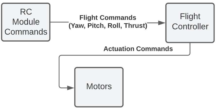
The vehicle was then configured to receive input commands from a remote control module as described below.
This is the A-tail control surface deflection in response to yaw commands
This is the A-tail control surface deflection in response to pitch commands
This full yaw control with thrust vectoring
Payload Component Testing
Most components were ready for testing near the end of the project lifecycle. The team had to scrap most testing plans and get creative as there was little time left.
TThe obstacle detection algorithm was tested on trees and birds as these objects would make up most of the obstacles the vehicle may run into. Images of the obstacles were printed and moved across the camera’s view. The gif shows the CV algorithms detecting the obstacles. The detection library outputs the location of the obstacles to build a MAVLink message that is sent to the flight controller. The controller then flies the vehicle to avoid the obstacles.
Next, the gifs below are from testing the winch control and show how the sampling protocol works. The winch is lowered when the vehicle arrives at a sampling location. This subsystem was developed by Danielle Laganiere.
If the capacitive water sensor is sensing water and there is some slack in the winch line, then the vehicle is at a valid sampling location.
If the strain sensor senses slack in the line and no water present, then it must be at an invalid location and retracts the sensor.
Lastly, the system checks for tension while retracting the water sensor. If tension is sensed, there could be a branch in the way. So the controller lowers and pulls the sonde multiple times until it is free. If this takes too long, an error message is sent to the ground station. In this case, the sensor was able to swing itself free.
Payload Delivery Vehicle Implementation
Vehicle Mechanical Design
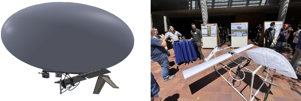
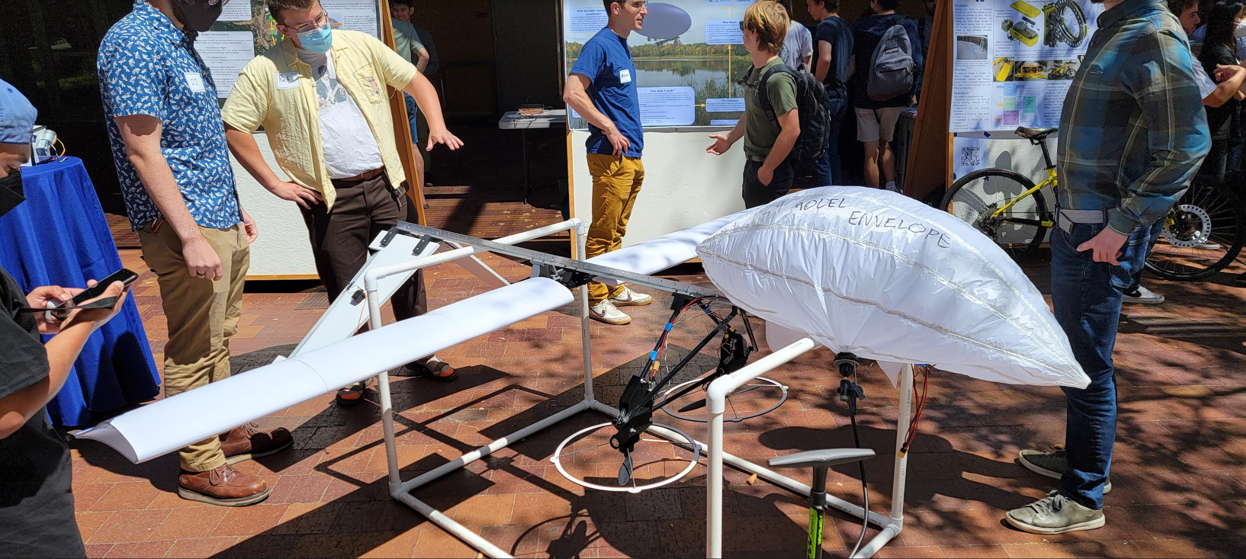
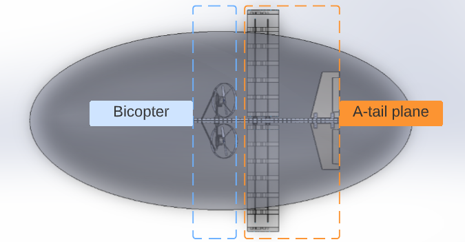
The images above show the final versions of the CAD and physically built UAV prototype. The vehicle has a central Aluminum spine with mounting points for the crucial components.
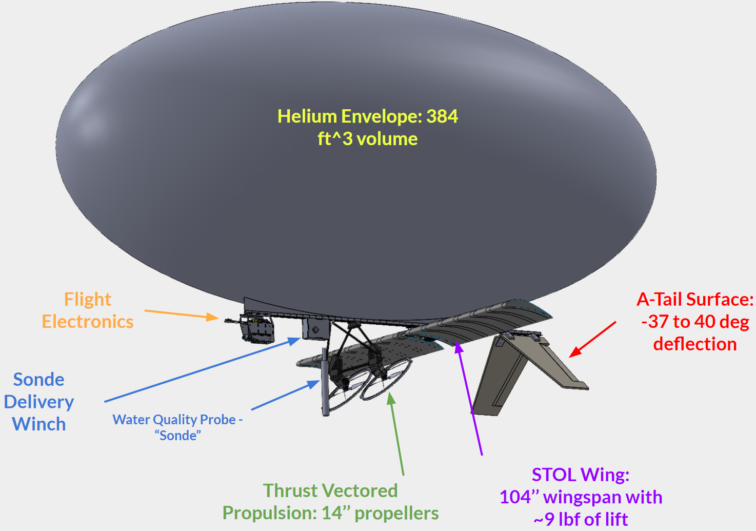
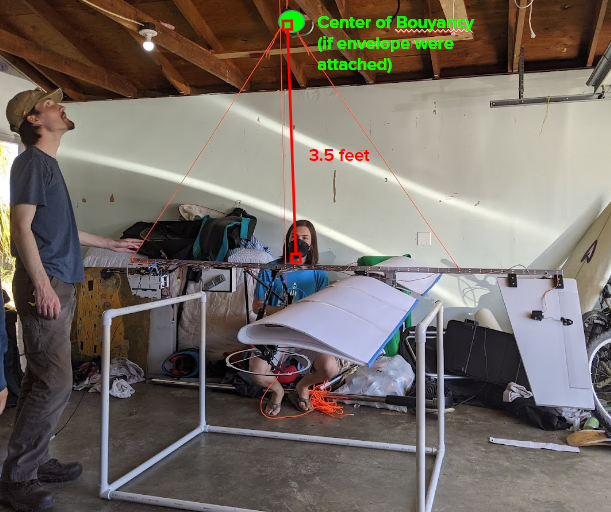
The vehicle has an A-tail ruddervator control surface followed by a STOL airfoil wing with a 104’’ wingspan to generate high lift at low speeds. The wing itself does not have ailerons as roll control is not a requirement. Next, a custom-built vectored thrust section comes to the fore of the wing. The thrust section is mounted at the vehicle’s center of gravity. After this, the flight electronics bay and payload deployment winch mechanism are also mounted to the vehicle. Finally, the 384 ft^3 helium envelope is mounted above the spine.
In summary, the vehicle has an A-tail control surface to be controlled by servos and thrust vectored propulsion from two BLDC motors whose vectors are controlled by two more servo motors.
Vehicle Electronics and Final Circuit
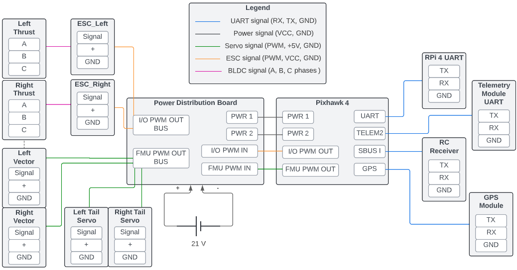
The circuit block diagram above shows the final iteration of the vehicle’s electronics. The brain of the system is the Pixhawk 4 Flight Computer. This device runs the customized ArduPilot software and sends commands to the vehicle’s actuators. There are two BLDC motors and four servo motors on the airship. Two of these servo motors are mounted on the A-tail's control surfaces, the other two are used to vector the thrust generated by the two BLDC motors. The BLDC motors are driven by 35A ESC chips which operate using DShot600 commands.
The Pixhawk 4 also connects to an external GPS module through UART as well as an SBUS receiver to capture radio communications sent from a remote control module. The Pixhawk also provides telemetry data to the ground station through a separate telemetry module. Finally, it is also connected to a Raspberry Pi 4 which runs the water sampling protocol and obstacle detection compute vision algorithms.
Vehicle Software
The software utilizes the open-source autopilot libraries provided by ArduPilot. ArduPilot provides community tested autopilot control loop source code for conventional UAV frames such as fixed wing planes, multicopters, and blimps. The team’s vehicle does not exactly fit into those categories as it is a mixture of multiple aircraft types.
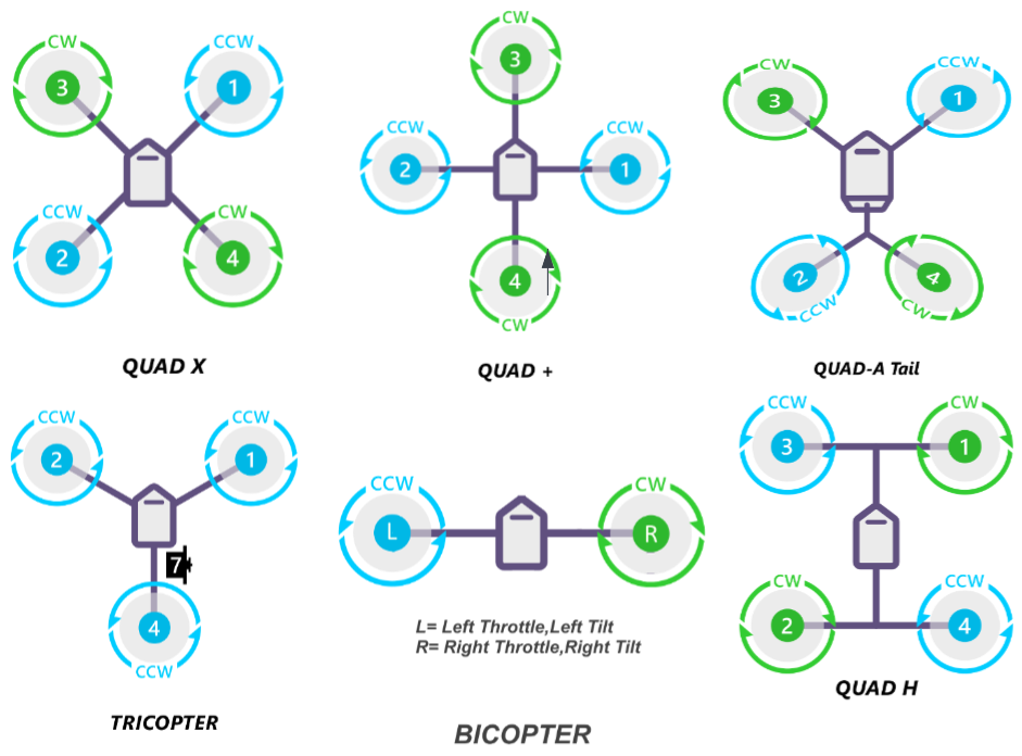
Through iterative design and development, it was found that using the base Multicopter/Bicopter ArduPilot model’s source code and customizing it to add A-tail surface functionality gave the best result. A breakdown of the vehicle’s actuators can be seen in the image below.
The software’s main loop, which runs at 400Hz on the Pixhawk 4, follows the diagram top level flowchart below.
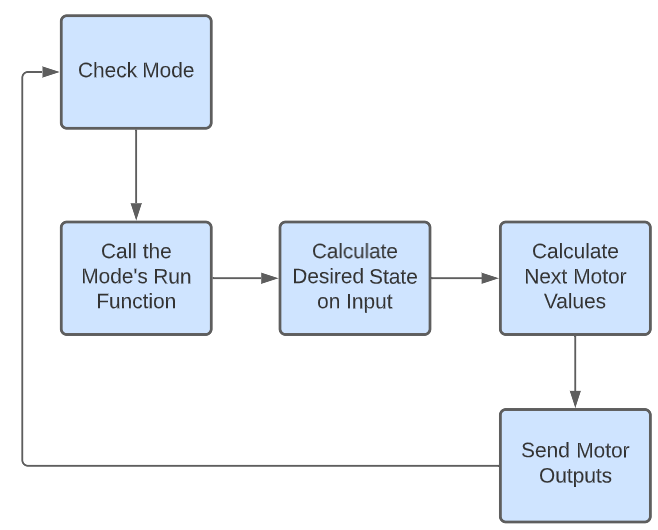
The software first determines which mode (Manual, Stabilize, Guided, RTL, etc.) it is in as that determines the desired behavior. Then it calls the mode’s respective run function. This function would then determine the necessary attitude commands and set the motor outputs to achieve the desired state. These commands are calculated based on their respective control loops. At a high level, each controller for yaw, pitch, and roll follows the following structure.
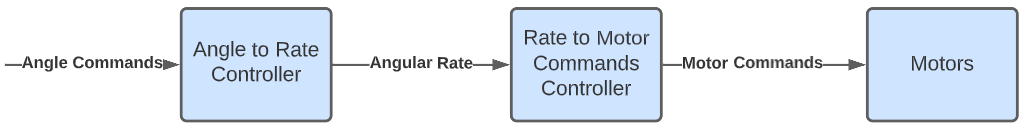
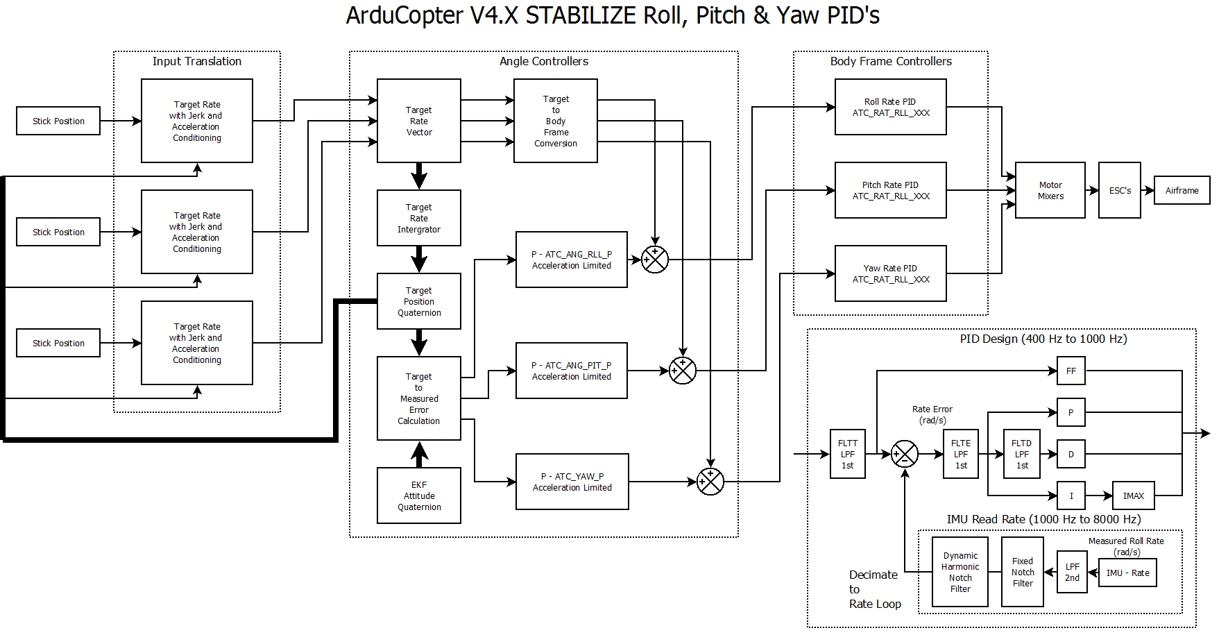
Each control loop translates input commands to angle rates which are then used to generate motor commands to push the vehicle to the desired state. Below is a more detailed description of how the loops are structured.
Motor Control
To ensure correct motor operation, a vehicle command to motor actuation table was made. The table details the expected motor behavior given any vehicle command. This was used to inform the autopilot design and verify the vehicle’s behavior.
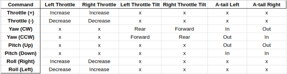
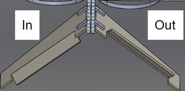
For context, this image describes the tail deflection direction
The UML diagram below shows how the C++ motor control library is set up
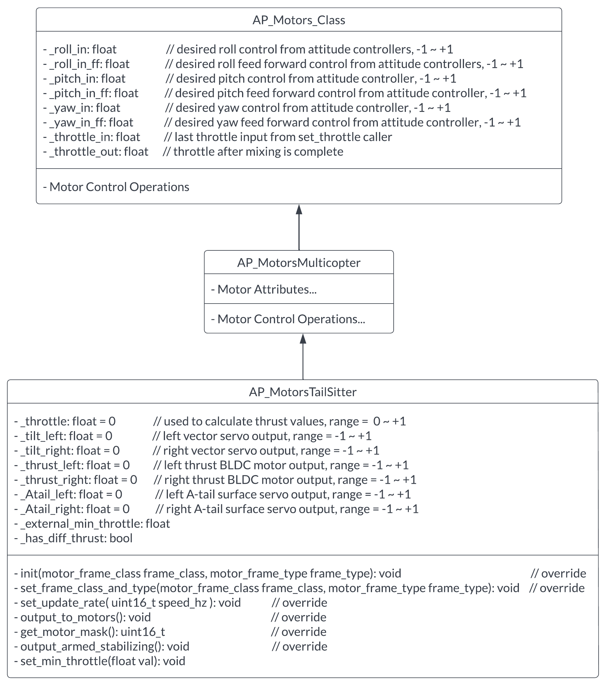
To control the vehicle’s motors, the software uses the AP_MotorsTailSitter motor class which inherits from the AP_MotorsMulticopter and AP_Motors_Class classes. It initializes the 4 motors required for thrust vectoring and can calculate the output for each motor. This class’s initialization function, AP_MotorsTailsitter::init(), was modified to set up 2 more motors used to control the A-tail. Then, using the pitch and yaw thrust values calculated in AP_MotorsTailsitter::output_armed_stabilizing(), the A-tail motor output is calculated as such:
_Atail_left = pitch_thrust - yaw_thrust
_Atail_right = pitch_thrust + yaw_thrust
Finally, AP_MotorsTailsitter::output_to_motors() is used to send new motor signals.
The A-tail motor commands are calculated based off pitch and yaw thrust values as these are the angles the tail surfaces are controlling.
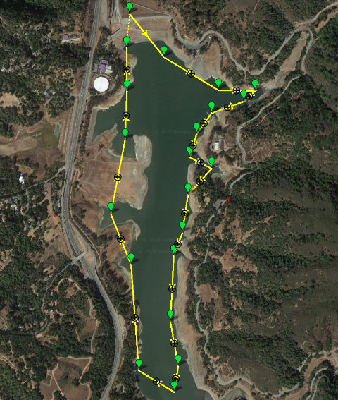
Mission Planning
One of the main reasons why ArduPilot was chosen is because it provides the pilot or user with the ability to create, simulate, and upload fully autonomous missions for the aircraft to follow. The team had chosen a test mission to sample the Lexington Reservoir. The mission is created through the MissionPlanner software interface as seen below and can be uploaded to any compatible flight controller unit such as the Pixhawk4 through USB.
Vehicle Status and Next Steps
As of June 2022, the vehicle can correctly respond to input commands from a remote-control module. Since these commands are the same as what would be sent in autonomous modes, the next steps are to rigorously tune each individual control loop in the software until reaching the desired stable outcome.
After this, simple tests to verify basic functionality such as Vertical Take-Off and Landing (VTOL), flying small distances, returning to home location, and switching between manual and autonomous modes. Once the vehicle passes all tests and checks, it is ready for full autonomous testing and eventually attempting an autonomous sampling mission.
Water Sampling Payload System Design
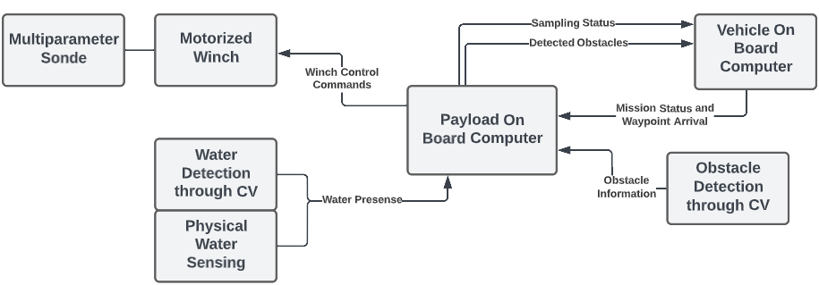
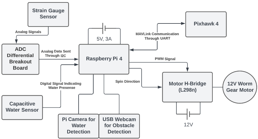
The diagram above shows the final iteration of the payload system. This was then translated to the circuit block diagram below.
Project Status and Next Steps
This project was for the UCSC Electrical and Computer Engineering Capstone 3 course series. As of June 2022, most core components were individually tested and verified or in the preliminary stages of integration. However, as the school year ended, the team members graduated and moved on to other projects.
If the team were to continue working on this project, the next steps for the vehicle would be stabilizing the spine with more rigid materials and beginning to tune the flight control loops. Next steps for the payload would be to finish integrating subsystems and test the full system. After this, the planned testing discussed above can be started.